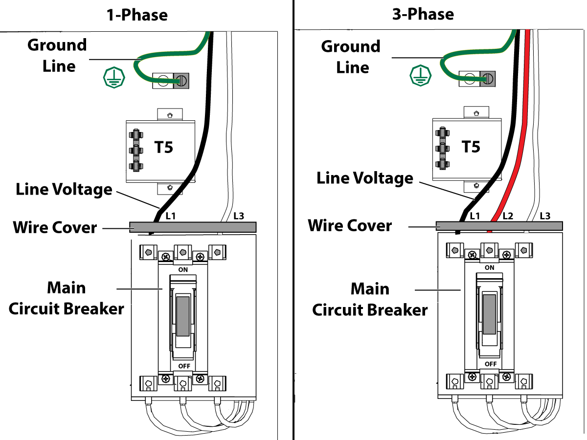
In this example for hayward pool pumps red will go to the l1 terminal and black will go to the l2 terminal.
Wiring pool pump motor l1 l2.
I am trying to run power to a 240volt electrical motor i bought but i do not know what the abbreviations mean and how to read the diagram that came with the new motor.
My electrical wiring project involves wiring a 240volt motor.
Most pool pumps use a 220 volt capacitor start induction run csi electric motor wired directly to a pool timer through a flexible conduit or whip.
There should be a diagram on the inside of the wiring compartment cover if you are wiring for v the three wires to the pool pump will be.
Ok i m installing a replacement pool pump and everything is going swimmingly get it but i just need to know where the black and red wires go to l1 or l2.
In both cases one was a red lion pump the other was something different the l1 and l2 terminals were not defined at least not where i could tell which was for hot and which neutral.
The green wire will be under the green screw to the far right.
The green ground wire connects to the green ground screw and the other two power leads will connect to the two power terminals marked usually l1 and l2.
It s a pentair superflo pump with a 230v motor and there s a post for l1 and a post for l2 and a post for the ground wire and i ve got a black wire a red wire and a green wire.
In addition there is a black plug with two wires coming from inside the motor a black wire and white wire with a black tracer line.
The pool timer acts like an automated switch.
In this example for hayward pool pumps red will go to the l1 terminal and black will go to the if you are wiring for v the three wires to the pool pump will be black white and green.
Wire a 240 volt motor electrical question.
Many pool pump motors use a thermal overload protector that prevents the motor s windings from overheating.
Simple job of removing a cover on the motor setting the jumper to the 115v settings and hooking up the black and white supply wires to l1 and l2.

